About
About the International Linear Collider
The International Linear Collider (ILC) will be a necessary tool for unlocking
some of the deepest mysteries about the universe. The ILC will allow physicists
to precisely explore extremely high-energy regions.
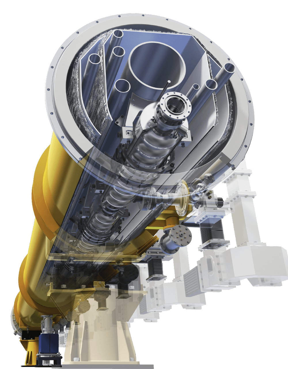
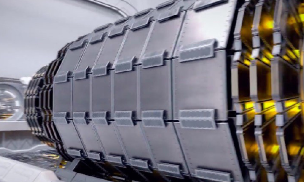
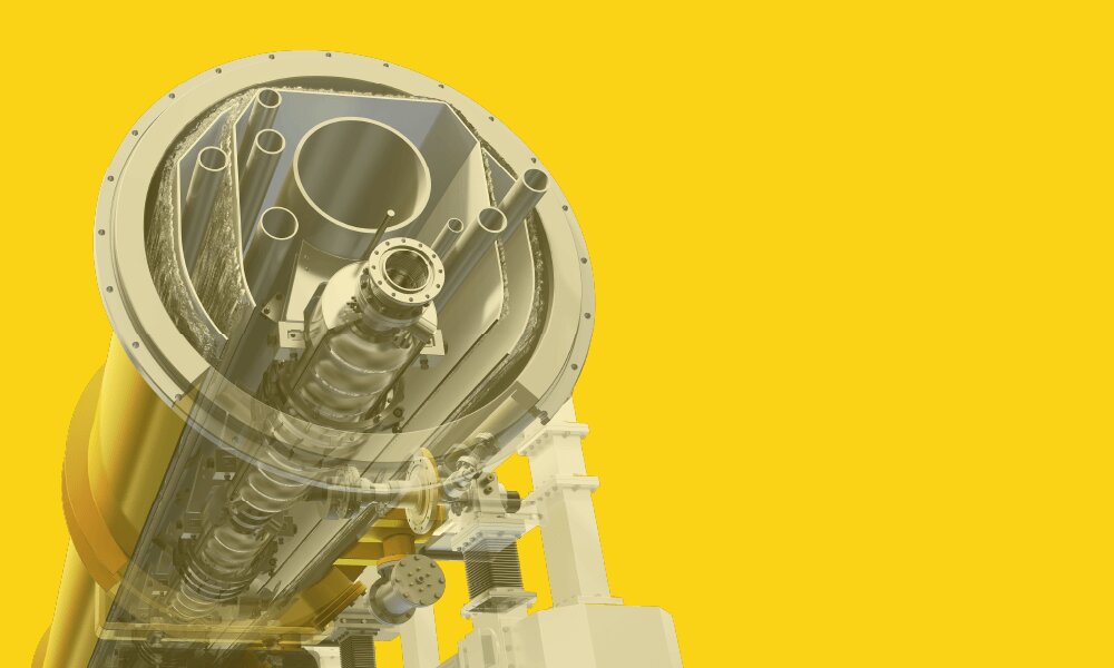
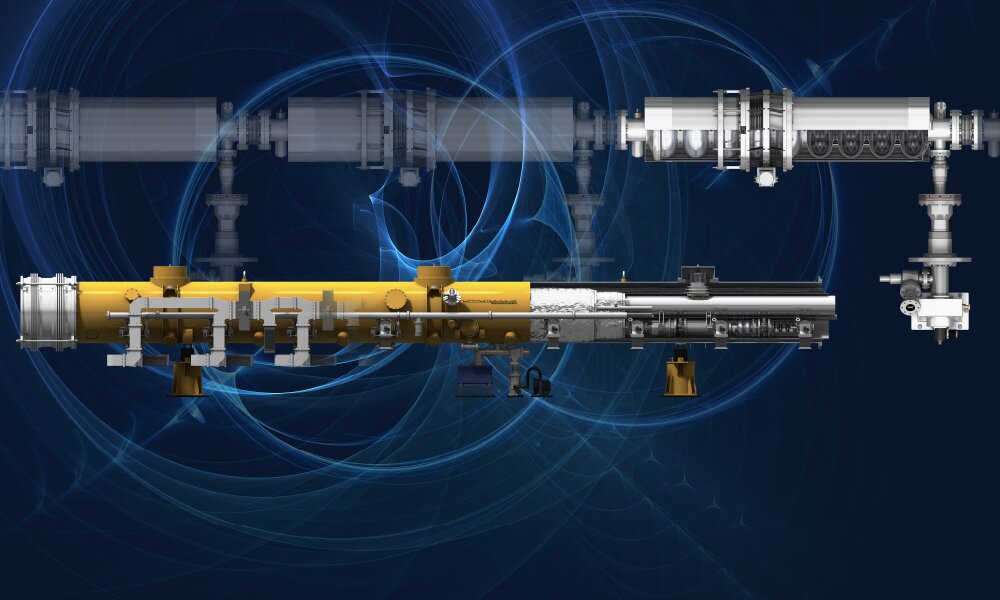
Consisting of two linear accelerators that will stretch approximately 20
kilometers in length, the ILC will smash electrons and their antimatter
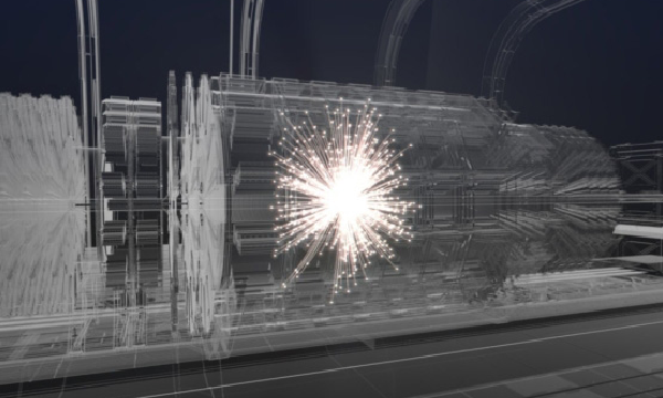
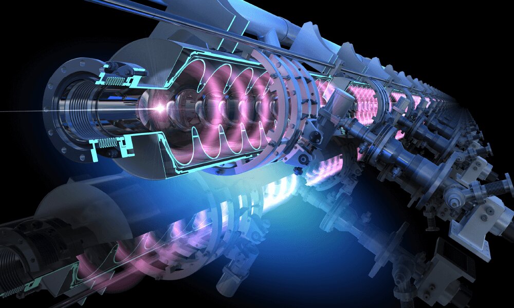
particles, positrons, together at nearly the speed of light. Colliding nearly
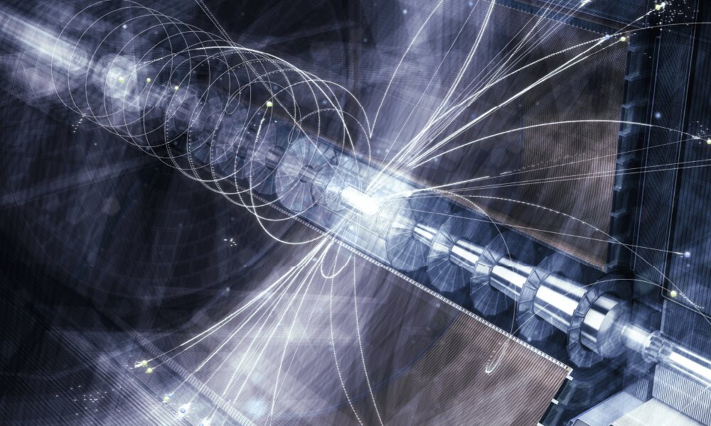
7,000 times every second, the electrons and positrons will create an array of
new particles that could help answer some of the most fundamental questions of
all time: What is the Higgs boson? What are dark matter and dark energy? Does
supersymmetry exist?