|
|||||||||||||
|
|||||||||||||
|
|||||||||||||
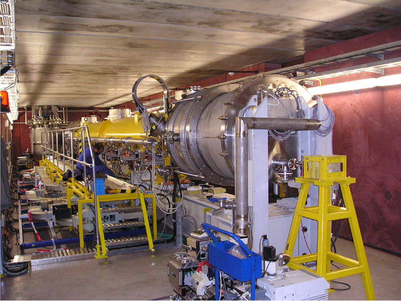
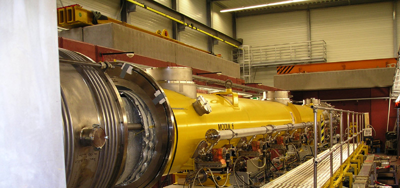
Module 6 has had a bit of a break since we last reported on its progress (NewsLine 11 May 2006 and NewsLine 15 June 2006). It spent the last few months in DESY’s new module test stand in a brand-new building – as sparkling as new buildings in research centres get – and hasn’t been idle. Several cooling cycles and all sorts of tests over several months made sure that its creators knew the exact behaviour of all cavities, cables and couplers, the slow and fast tuners and the magnet. The new test stand was built for the European X-ray free-electron laser project XFEL and its smaller brother FLASH (for “Free-electron LASer in Hamburg”) which has been in operation since August 2005. It is the first test stand that can house whole modules and will be extremely useful for R&D for ILC modules. These modules, containing the cavities and thus the heartbeat of the machine, will look a lot like the ones that are driving FLASH at the moment. Before the test stand existed whole modules were tested in the FLASH accelerator, but with the new building there’s both more time and space – and thus much more detail in the results. The module is cooled down and heated up ten times. During each of these thermal cycles, lasting roughly four days, the performance of each cavity is carefully monitored. Couplers are tested in batches of four, which is more efficient and also solves an old problem: couplers have always been a weak point because they are a potential place where cold can leak out (or heat in), which would cause mayhem inside the cryomodules. “We compare the performance of the cavities at each cycle and thus get a full picture of how they behave and whether there are leaks,” says Rolf Lange, work package leader at DESY for XFEL accelerator modules and team leader for module tests. The axis on which the cavities and the magnet are adjusted can be tested and controlled to very high precision during the whole test, which will be very important for the ILC.
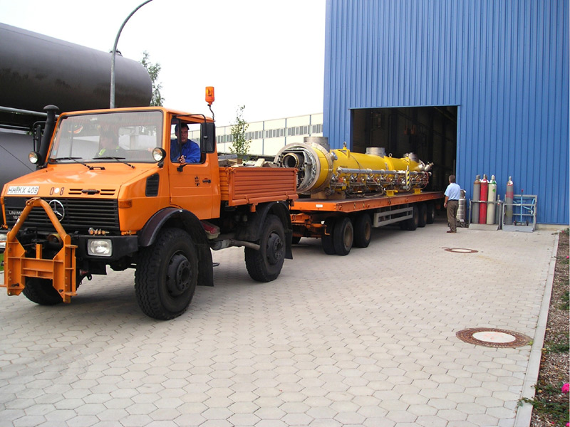
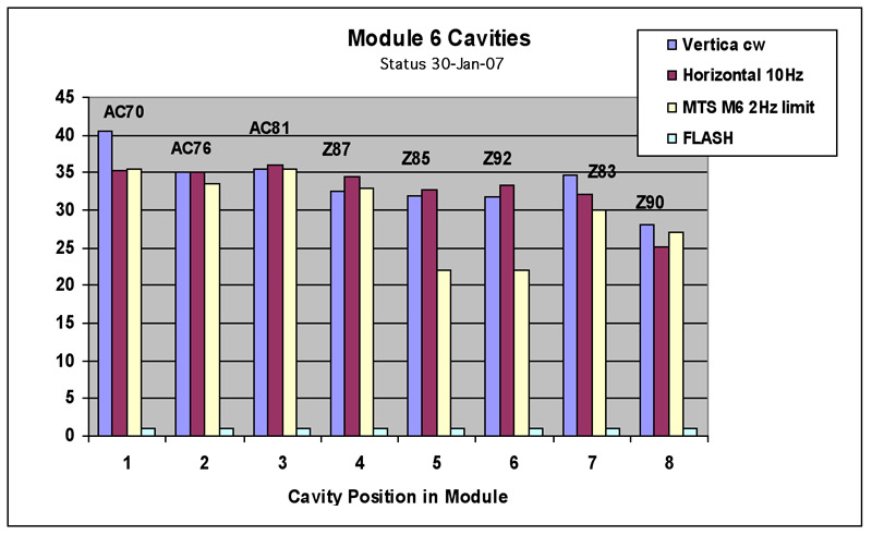
No movement of the module will go undetected because vibration meters are installed at many points - attached to the magnet inside the module and on the outside, where their position can be changed. They measure the module’s movement (or vibrations) under all conditions – warm, cold, with RF, without RF and with trucks going past…the measurements will be very useful for the construction of the European XFEL and become crucial when planning for the ILC becomes site-specific. ”ILC test subject” Module 6 is now probably the best-known cryomodule ever. However, best-known does not imply best-understood: Even though there weren’t any leaks and six of the cavities performed wonderfully, each reaching the designated gradient of 34 megavolts per metre, there were two odd ones out that only reached 22 megavolts. “This is not dramatic as FLASH requires an average gradient of 26 megavolts per metre and Module 6 still delivered 30, but we would still like to understand what makes them different from the rest because all eight cavities had exactly the same treatment,” explains Rolf Lange. Module 6 will be inserted into FLASH in April. All future modules will spend time in the test stand – anything between two weeks and four months is possible. -- Barbara Warmbein |
|||||||||||||
| © International Linear Collider |